


Network configuration under SERVERware
Introduction
On this page, you will get precise information on the network design for SERVERware 4 based on two different approaches.
First, you will get a description of the SERVERware 4 network without redundancy support at the network level.
The second approach is the network design based on redundancy at the network level, which will enable high availability of services.
To obtain high-availability systems that will provide fault-tolerant services with minimal or no service interruption, the network design planning must be based on redundancy at all levels. This means that all important network components must be redundant. This document will cover the switching level, let's say up to the second network layer. The routing level depends on the global network design and can differ from one case to another.
This example of network design is based on the switches in the series Cisco WS-C3750G .
This layer 3 switch supports all the protocols and mechanisms required for redundancy.
The Cisco WS-C3750G switch is capable of delivering the following performance:
- 32 Gbit/s switching fabric
- Stack transfer rate of 38.7 mpps for 64-byte packets
- Transfer rate: 6.5 to 38.7 mpps depending on the model
We will also track the features of the switch that we will use to achieve network redundancy:
Cisco CrossStack UplinkFast (CSUF) technology provides increased network redundancy and resilience through fast Spanning Tree convergence.
(less than 2 seconds) on a switch stack using Cisco StackWise technology.
The 1:N master redundancy allows each member of the stack to serve as master, thus offering the highest failover reliability.
Cross-Stack EtherChannel offers the ability to configure Cisco EtherChannel technology across different stack members for high resilience.
The IEEE 802.1w RSTP (Rapid Spanning Tree Protocol) provides rapid Spanning Tree convergence, independent of Spanning Tree timers, and also offers the benefit of distributed processing.
Stacked units behave like a single Spanning Tree node.
Per-VLAN Rapid Spanning Tree (PVRST+) allows fast spanning-tree reconvergence on a per-VLAN spanning-tree basis, without requiring the implementation of multiple spanning-tree instances.
Bandwidth aggregation up to 16 Gbps with 10 Gigabit EtherChannel technology, 8 Gbps with Gigabit EtherChannel technology, and up to 800 Mbps with Fast EtherChannel technology improves fault tolerance and provides faster aggregate bandwidth between switches and to individual routers and servers.
Non-redundant network

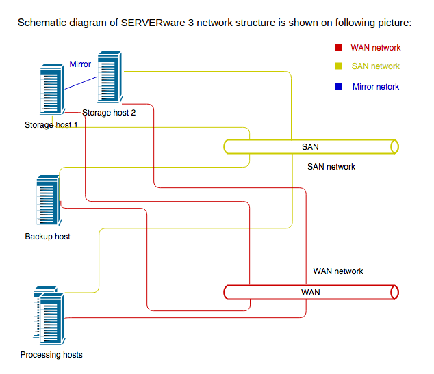
The diagram above shows the typical configuration of SERVERware 4.
The system is built around storage hosts, processing hosts, and backup hosts. Two storage hosts configured to work as mirrors provide storage for the processing hosts on SAN (Storage Array Network). The processing hosts run locally on the VPSs provided on the storage network. The VPSs use the WAN network to provide services to the customer.
The backup host provides disk space for backing up the VPSs. Backup hosts use the storage network to transfer data from the storage hosts to the local backup disk space.
Due to the nature of storage traffic, we need to separate SAN traffic from other traffic on the network. In the case where we have many processing hosts, the best solution is to use a dedicated network switch that serves the network traffic. In reality, we will use the same switch for the SAN and any other traffic.
In this case, we need to separate the traffic by using the VLAN concept. Thus, for SAN traffic, a SAN VLAN will be created. Other traffic we can keep in the default native VLAN. Optionally, we can create VLANs for voice traffic and configure the priority of this traffic.
The following schematic diagram shows the SERVERware 4 network with a Cisco switch (no network redundancy):
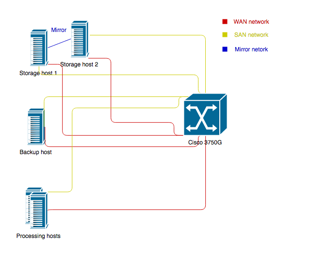
To separate SAN traffic from other traffic on the network, we can use VLANs and configure all ports belonging to the SAN network to be members of the SAN VLAN.
Here is a Cisco configuration example that shows how to configure VLANs on the ports:
... interface GigabitEthernet0/0/1 switchport access vlan 20 switchport mode access ! interface Vlan20 description “SAN VLAN” no ip address ... Redundant network
The SERVERware 4 network design with redundancy at the network level is based on two network switches connected and configured to operate in a stack.
The schematic diagram of SERVERware 4 network redundancy is shown in the following image:
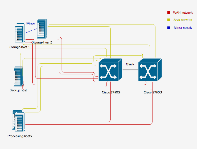
As shown in the diagram above, the redundant network is based on two switches Cisco WS-3750G . The switches are connected in a stack using appropriate stacking cables. The WS-3750G stacking bus supports 32 Gbit/s. Since we have two switches, the hosts must be connected to both switches. This means that for each connection (SAN, WAN), the host must have two Ethernet interfaces connected to the two switches.
This network design allows for redundancy at the network level. In case of a switch failure, another switch will take over the network traffic.
The Cisco switch supports EtherChannel on switch stacks, which is necessary, and without it,
the network redundancy will not work.
In the same way that we ensure the separation of SAN traffic in the non-redundant network design, in the redundant network design as well, to separate SAN traffic from other traffic, we will configure the appropriate VLANs. Here is an example Cisco switch configuration with network redundancy and VLANs configured to separate SAN traffic:
interface Port-channel5 switchport access vlan 20 switchport mode access ! interface Port-channel6 switchport access vlan 20 switchport mode access ! interface Port-channel7 switchport access vlan 20 switchport mode access ! interface Port-channel8 switchport access vlan 20 switchport mode access ! … interface GigabitEthernet1/0/25 description Controller 1 SAN NIC switchport access vlan 20 switchport mode access channel-group 5 mode active spanning-tree portfast ! interface GigabitEthernet1/0/26 description Controller 2 SAN NIC switchport access vlan 20 switchport mode access channel-group 6 mode active spanning-tree portfast ! interface GigabitEthernet1/0/27 description Backup SAN NIC switchport access vlan 20 switchport mode access channel-group 7 mode active spanning-tree portfast ! interface GigabitEthernet1/0/28 description Proco SAN NIC switchport access vlan 20 switchport mode access channel-group 8 mode active spanning-tree portfast ! … interface GigabitEthernet2/0/25 description Controller 1 SAN NIC down left switchport access vlan 20 switchport mode access channel-group 5 mode active spanning-tree portfast ! interface GigabitEthernet2/0/26 description Controller 2 SAN NIC down left switchport access vlan 20 switchport mode access channel-group 6 mode active spanning-tree portfast ! interface GigabitEthernet2/0/27 description Backup SAN NIC down left switchport access vlan 20 switchport mode access channel-group 7 mode active spanning-tree portfast ! interface GigabitEthernet2/0/28 description Proco SAN NIC down left switchport access vlan 20 switchport mode access channel-group 8 mode active spanning-tree portfast ! interface Vlan20 description "SAN VLAN” no ip address ! In the example above, two SAN Ethernet interfaces of controller 1 are connected to Gigabit port 25 of switch 1 and Gigabit port 25 of switch 2. These two ports on switch 1 and switch 2 form the Ethernet Port-channel5. On this Ethernet port is configured VLAN 20, which is the VLAN for the SAN network. Controller 2 is connected to gigabit port 26 of switch 1 and gigabit port 26 of switch 2. These two ports of switch 1 and switch 2 form the Etherchannel Port-channel6. On this Ethernet port is configured VLAN 20, which is the VLAN for the SAN network. The same is configured on the backup and processing hosts.
This is how network-level redundancy is configured.