



16. Network
The menu Network allows you to add, configure and remove logical subnets in SERVERware.
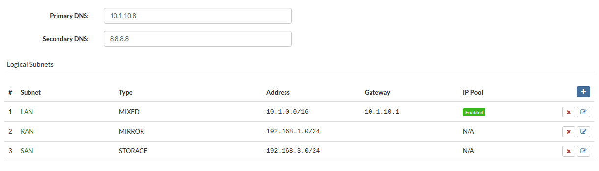
Adding a logical subnet
To add a logical subnet, follow these steps:
In the menu Settings, select the Network option, then click the button Add.
A dialog box to add a logical subnet appears. Select the type, enter the name and other relevant network information.
Check the box Use this subnet for the VPS network, and provide the name of the bridge interface if you need this subnet for VPS networking.
You can use the netsetup tool to preconfigure the bridge interface with the same name on all hosts of the SERVERware cluster.
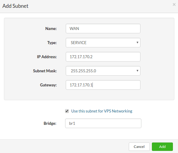
Click the button Add to create the logical subnet.
Deleting the logical subnet
Follow this procedure to delete a logical subnet:
- In the menu Settings, select the option Network.
- Click on Remove next to the logical subnet you want to delete. A confirmation dialog box appears.
- Click on Yes. The logical subnet disappears from the list.
IP pool extension
To configure an existing logical subnet, proceed as follows:
In the menu Settings, select the option Network, choose the logical subnet you want to configure, and click Configure.
This will open the subnet configuration dialog box.
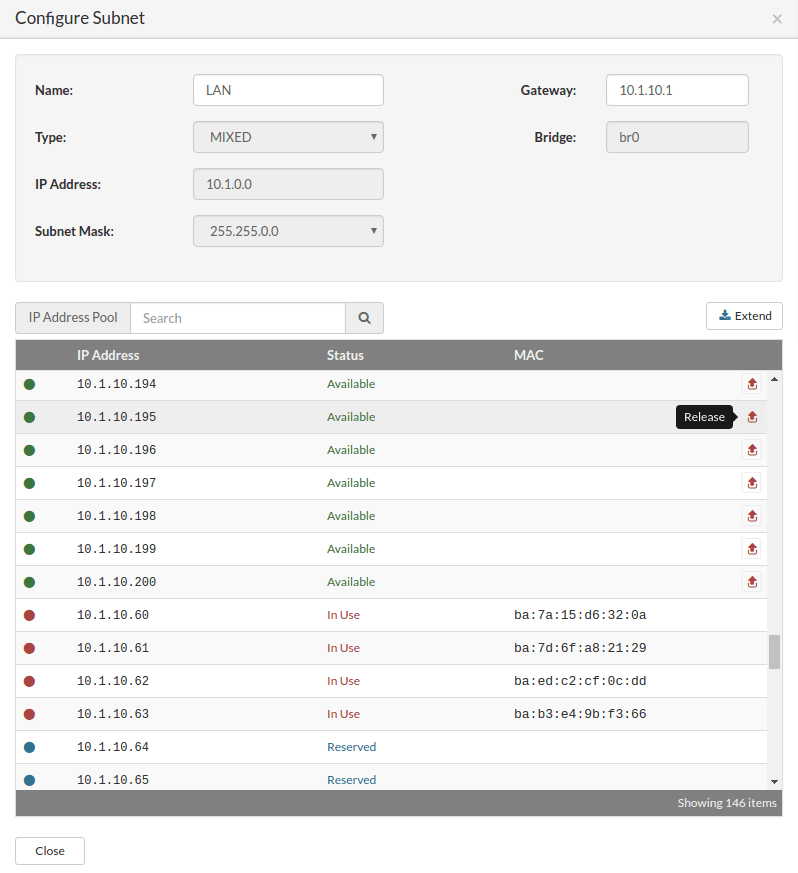
To expand the IP address pool, click the Expand button.
The dialog box Expand the IP address pool will appear.
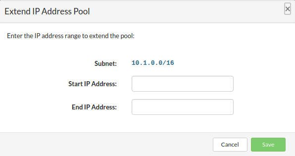
Enter the range of IP addresses you want to add to expand the pool, then click Save to extend the IP address pool.
Once finished, click Close to exit the subnet configuration dialog box.
Deleting the IP address from the pool
To remove an IP address from the pool, follow these steps:
In the menu Settings, select the option Network, choose the logical subnet you want to configure, and click Configure. This will open the subnet configuration dialog box.
To remove an IP address from the pool, click the button Release next to the IP address in the list.
A confirmation dialog box will appear.
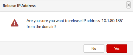
Click on Yes to confirm the release of the IP address.
Once finished, click Closesr to exit the subnet configuration dialog box.
Create an IPV4 virtual network interface
Network virtualization enables communication between multiple machines (VPS). While physical networks connect computers through cables and other hardware equipment, virtual networks extend these capabilities through the use of software management to link computers and servers over the Internet. This approach uses virtualized versions of traditional networking tools, such as switches and network adapters, enabling more efficient routing and easier changes to the network configuration.
Virtual networks allow devices spread across multiple sites to operate with the same capabilities as a traditional physical network. This provides network administrators with new options for creating network connections between VPSs more efficiently, while offering greater flexibility in providing network resources according to specific needs and applications.
One of the essential features is the ability to move workloads within the network infrastructure without compromising service levels, security, and availability.
To create a new IPv4 virtual interface, you must first add a new virtual network by following these steps:
In the main menu, go to Settings > Network.
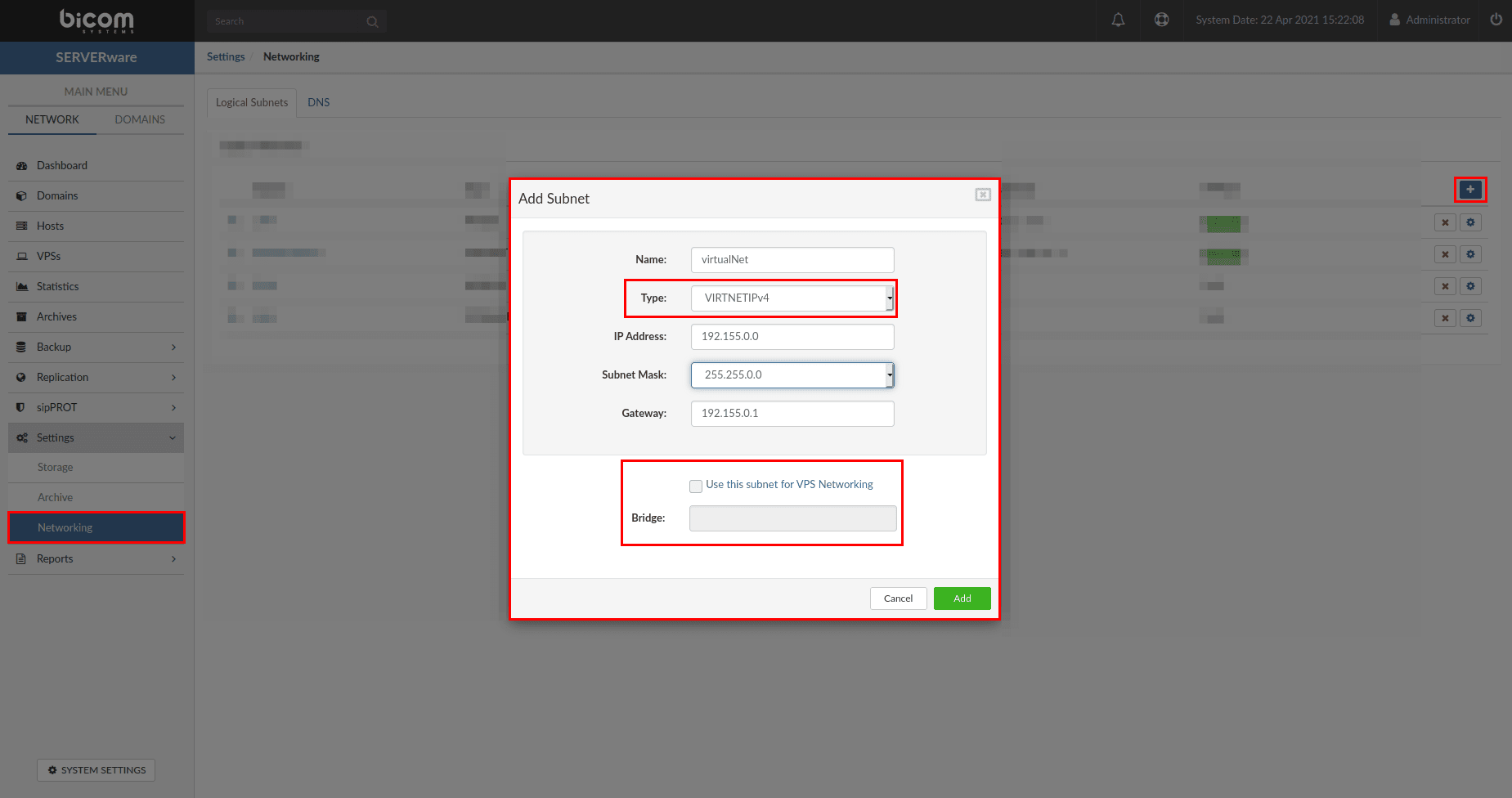
Once all fields are filled in, click the button Add to finalize the creation of the new virtual network.
You must now add some IP addresses to the IP pool of the network you just created. To do this, click the small gear icon next to the newly created network.

Then select Initialize | Extend and enter the address range you want to add to the new virtual network.
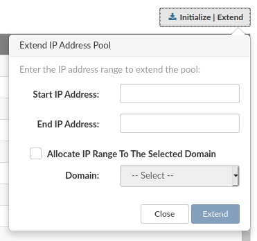
Optionally, you can automatically assign the range to the selected partition.
Finally, you must modify or create a VPS. In the Network tab of the selected VPS, add the new virtual interface and select an address from the pool.
Create an IPV6 Virtual Network interface
To create a new IPv6 virtual interface, follow these steps:
In the main menu, go to Settings > Network.
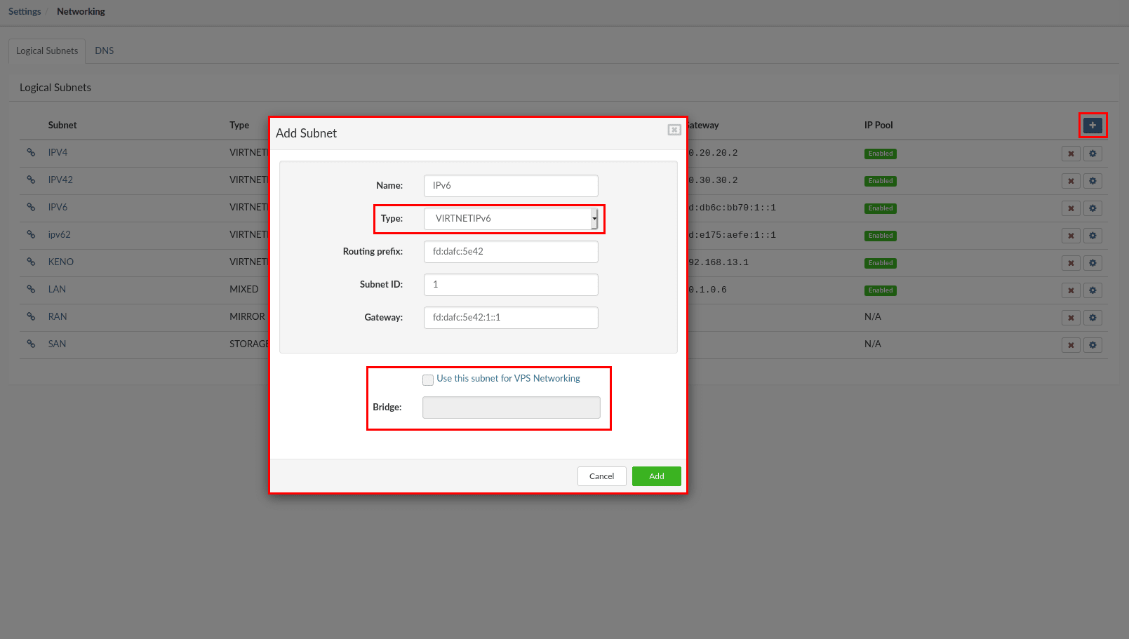
In the top right corner, click the button +. A pop-up window will be displayed, containing the network interface settings.
Fill in the required fields as follows:
- Name : enter the name of the new network (limited to 15 characters).
- Type : in the drop-down menu, select VIRTNETIPv6 for the network (there are two options for virtual networks, VIRTNETIPv4 for IPv4 and VIRTNETIPv6 for IPv6).
- Routing prefix : enter the routing prefix of the IPv6 network (SERVERware will automatically fill in this field). ** Example for IPv6: fd:ce8c:54b5
- Subnet ID : specify the subnet ID for the selected network. ** Example for IPv6: 1
- Gateway : indicate the default gateway (the gateway address will be added to the SERVERware CONTROLLER, which will act as a gateway/router for the virtual networks). ** Example for IPv6: fd:ce8c:54b5:1::1
DNS zones
The DNS plugin allows the SERVERware controller to be used as the authoritative partition name server and to be able to resolve the address of each VPS based on the SERVERware database.
For example, SERVERware can be assigned a domain zone cluster1.mondomaine.com, and it will be able to resolve the IP addresses of each host and VPS it is responsible for, based on the given VPS name, for example, pbx1.cluster1.mydomain.com.
Based on the client's source address, this plugin will resolve the VPS IP addresses from the corresponding private or public networks.
Immediate benefits:
- VPSs can change their IP address or network while remaining accessible via the domain name, without requiring additional configuration changes on the DNS, because SERVERware is authoritative for a given zone.
- This can be used as an SRV record mechanism for service discovery, simplifying DNS management for service providers with multiple services, since they only need to forward requests to SERVERware.
- This gives us the ability to deploy several public DNS instances via the device provisioning feature in PBXware and connect them in real time with SERVERware, thereby eliminating caching issues with third-party resolvers.
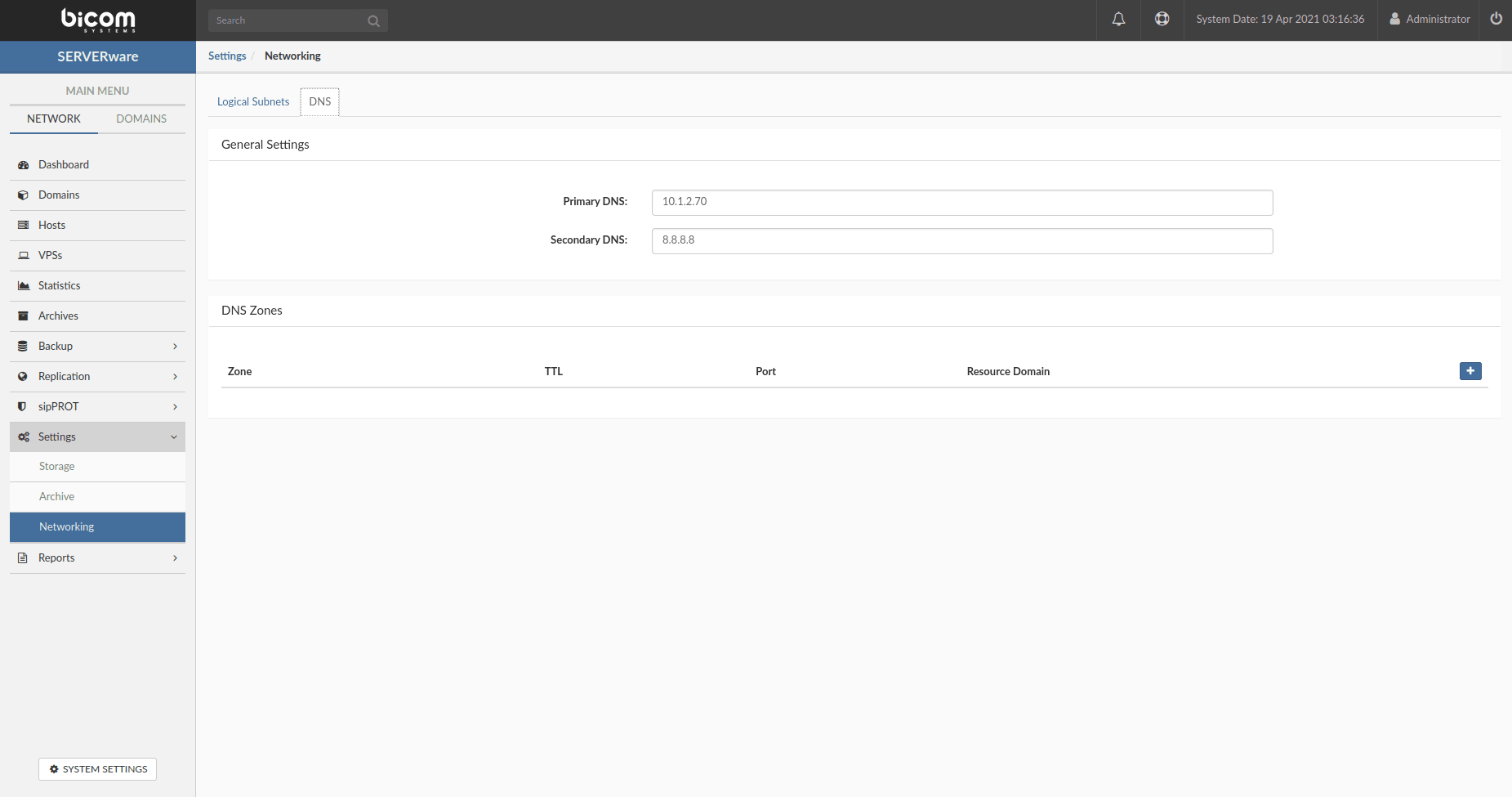
To configure the DNS zone, follow these steps:
- Go to the Network > DNS tab.
- Click the Add new zone button.
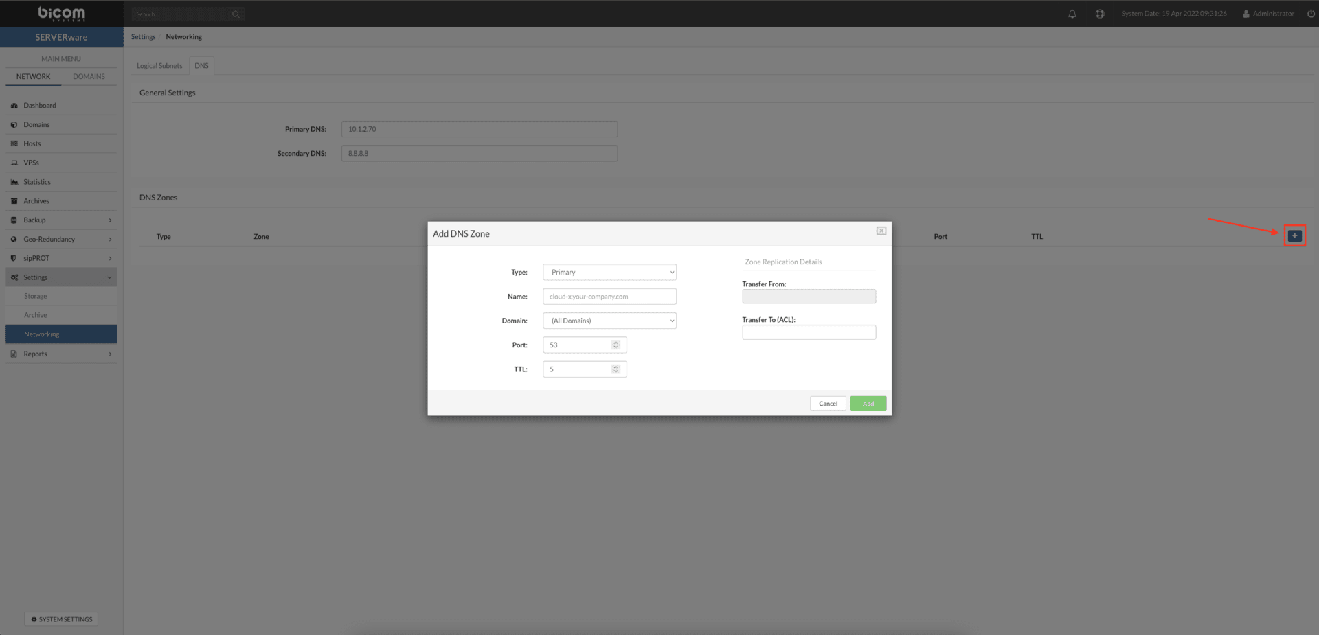
Fill in the fields as follows:
- Type : Select the role of the primary or secondary server from the drop-down list.
- Name : Add your domain name, for example, server1.mydomain.xyz in the field Name (this will be the resolution name of your DNS zone).
- Domain : In the drop-down list, select the domain to restrict the DNS record to the selected SERVERware domain (the default selection will use all domains available on the SERVERware).
- The default port is 53, it is the default port for the search DNS (Domain Name Server) and must not be changed unless required by your network administrator.
- The TTL is a parameter that tells the DNS resolver how long to cache a query before requesting a new one. The information collected is then stored in the local resolver cache for the TTL before being retrieved to gather new updated details.
- The field Transfer from must be filled in with the IP address of the primary server in the DNS zone and will only be enabled if the Type is set to secondary.
- In the field Transfer to (ACL), enter the IP addresses of the servers you wish to specify. The application allows the servers to send the DNS zone data to the specified secondary server.
- Press the SAVE button to successfully add your DNS zone.
